|
Solo Controller Documentation 1.0
Documentation for the Solo Controller
|

|
|
Solo Controller Documentation 1.0
Documentation for the Solo Controller
|
|
Related sub-pages include:
Discuss features of the Controller Circuit.
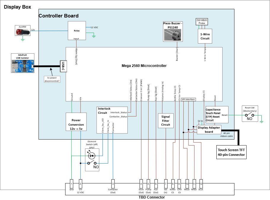
The four components that make up the control electronics are as follows:
The Arduino Mega 2560, Rev 3 microcontroller is the "brains" for the control electronics. The software loaded onto the microcontroller is here. Documentation describing the software architecture is here.
The Solo Controller uses a 7 inch, 1024x600 pixel TFT display from BuyDisplay.com. Model ER-TFT070A2-6-5633 was selected. This display has built in Capacitance Touch Panel (CTP) capability. Information about the CTP capability can be found in the CTP Datasheet and the CTP Data Register documentation.
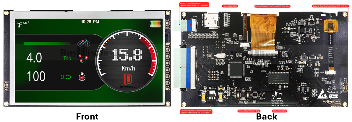
The display has a built in MicroSD Card Interface, which is not used by the Solo Controller. It can also be upgraded, by soldering a 128M bit (SOP8) ROM chip to the board. This gives more than enough non-volatile storage capacity to hold the imagery used by the Solo Controller software. Finally, the display includes a LT7683 graphics chip. the LT7683 has 128Mb of built in RAM. This chip provides the graphics engine that drives the Solo Controller user interface.
We use the ER-AS-RA8875 display adapter from BuyDisplay.com to drive the TFT. The ER-AS-RA8875 has the same pin configuration as the Mega 2560 microcontroller. So, it is designed to plug in to the mega as a Top-hat card. The microcontroller communicates with the TFT display via a 4-pin SPI interface. The SPI signals are sent to the ER-AS-RA8875 via the Mega pins. The interface card then translates this into the format required by the TFT, communicating via a 40-pin ribbon cable.
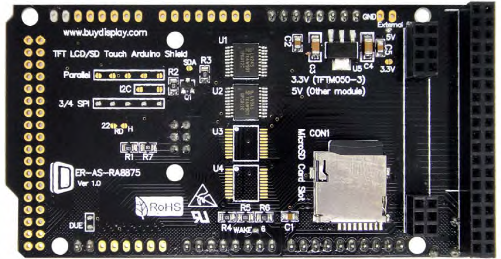
It is important to note that the TFT requires about 1A of current at 5V. The power regulator on the Mega 2560 doesn't have enough capacity to provide this. Therefore, external power must be provided to the ER-AS-RA8875. The interface board used for this project has a 3.5x1.35mm DC barrel connector. The 5W of power that is needed is provided by the Solo Controller Interface Board, described below. A short cable is run from the JST power connector on the Solo Controller Interface Board to the DC connector on the ER-AS-RA8875.
Further documentation on the ER-AS-RA8875 can be found here and here.
The Solo Controller Interface Board is a custom board, created for the Solo Controller. This board serves a number of roles:
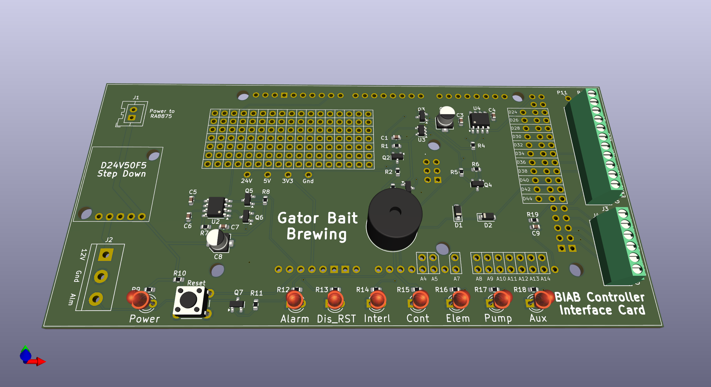
Detailed information can be found on the Controller Interlace Board page.
The following pictures show the physical layout of the electronics components:

The SPI interface between the Mega 2560 and the LT7683 graphics chip on the TFT is very slow. It can take as much as 5 seconds to transfer a 12-bit color, 1024x600 pixel image from the microcontroller to the LT7683. This is far too slow to be useful for the Solo Controller User Interface. Therefore, the microcontroller is only used to send commands to the LT7683. Images are not sent across this interface.
Instead, we use one of the following two methods to display imagery on the TFT
Coming soon... Discuss how images are pre-loaded into the ROM on the TFT. Commands sent to the LT7683 can transfer the images from ROM into RAM. Once in RAM, the images can either be displayed or manipulated via the Bit Transfer Engine provided by the LT7683.
Talk about where menu images are stored. 12-bit format
Talk about where fonts are stored. talk about format. provide link to more information about font handling.
Coming soon... Talk about the use of native graphics capabilities of the LT7683. This can be used to quickly draw lines, rectangles, ellipses, etc. Describe how this is used in conjunction with the menu graphics.