|
Solo Controller Documentation 1.0
Documentation for the Solo Controller
|

|
|
Solo Controller Documentation 1.0
Documentation for the Solo Controller
|
|
The Controller Interface board acts as an interface between the Mega 2560 microcontroller and the RA8875 Display Interface card, providing the custom features needed to implement Solo Controller functionality.
The Controller Interface Board was designed in KiCad 9.0. The circuit diagram and PCB layout can be found in the Solo Controller Github repository. An interactive BOM, showing the layout of PCB components can be found here.
Some of the key features of the card include:
Since this card is intended as a prototype card, a number of additional features have been added to help prototype and debug new features. This includes:
Future, production version of this board may remove these additional features.
The following is the primary circuit diagram for the Solo Controller Interface Board. Note that there are two sub-diagrams shown here: CTP Reset Circuit and the Power Interlock circuit. Diagrams for these circuits are below.
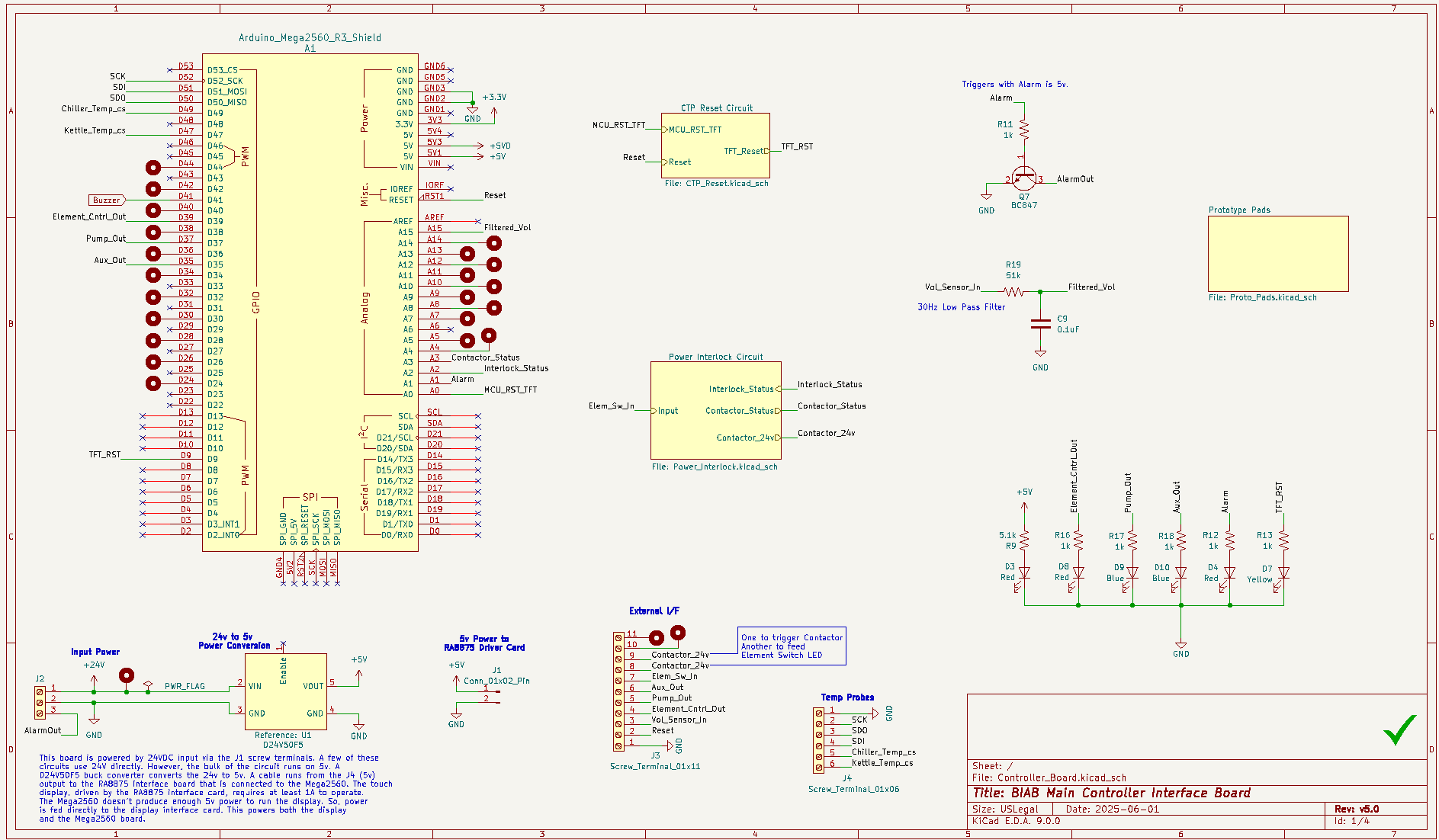
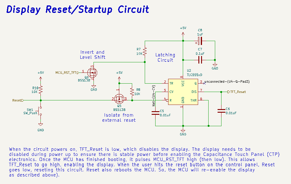
The Capacitance Touch Panel (CTP) circuit provided by the ER-TFT070A2-6-5633 display, has specific power on requirements. In particular, the TFT reset pin must remain grounded during power up. Once the power is stable, the reset pin can be allowed to float, which returns it to 5v. This enables the TFT, making it ready for successful operation. Failure to do this will can place the CTP module into a bad state.
The CTP Reset Circuit uses a 555 timing chip to ground the reset pin during system power up. ONce the microcontroller has completed it's startup, it briefly pulses the A0 pin high (5v) before returning it to ground. This triggers the 555 timing chip, latching the CTP in the enabled state.
The reset pin in this circuit is tied to a momentary button in the Display Enclosure. If this button is pressed, reset is grounded. When this happens, the microcontroller reboots and the CTP Reset Circuit disables (grounds) the CTP reset. As described above, once the microcontroller completes its boot sequence, the TFT is enabled.
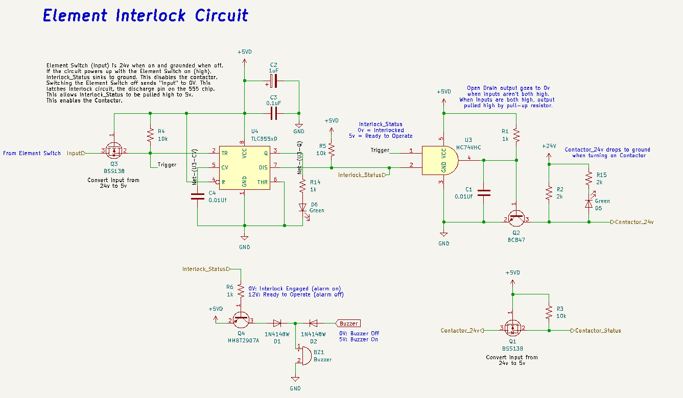
The Solo Controller has an Element Enable switch designed to enable/disable the heating element within the kettle. The Element Interlock circuit ensures there we always have full control of the heating element during system startup. Should the Element Enable switch be 'on' during system power up, the 'input' pin in the Element Interlock circuit will be set to 24v. This sets 'Interlock_Status' to 0v, disabling the element. Should this happen, the buzzer will turn on, giving the users an audible indication of the error condition.
Placing the Element Enable switch into the 'off' position, forces 'input' to be 0v. This action latches 'Interlock_Status' at 5v, which enables the contactor for the element.
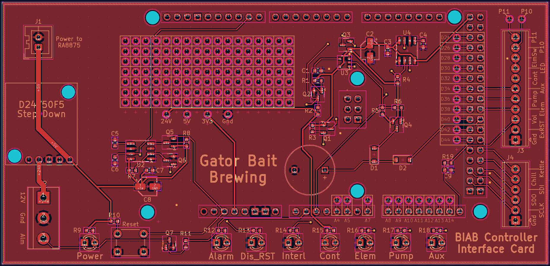
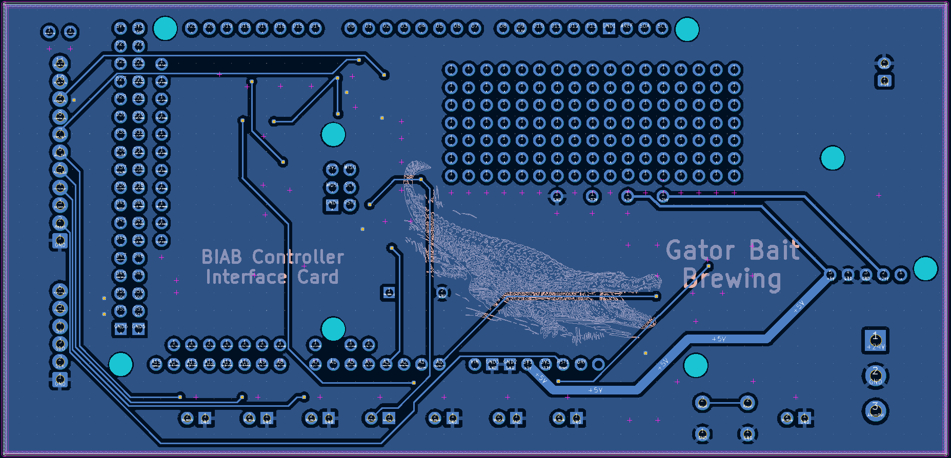
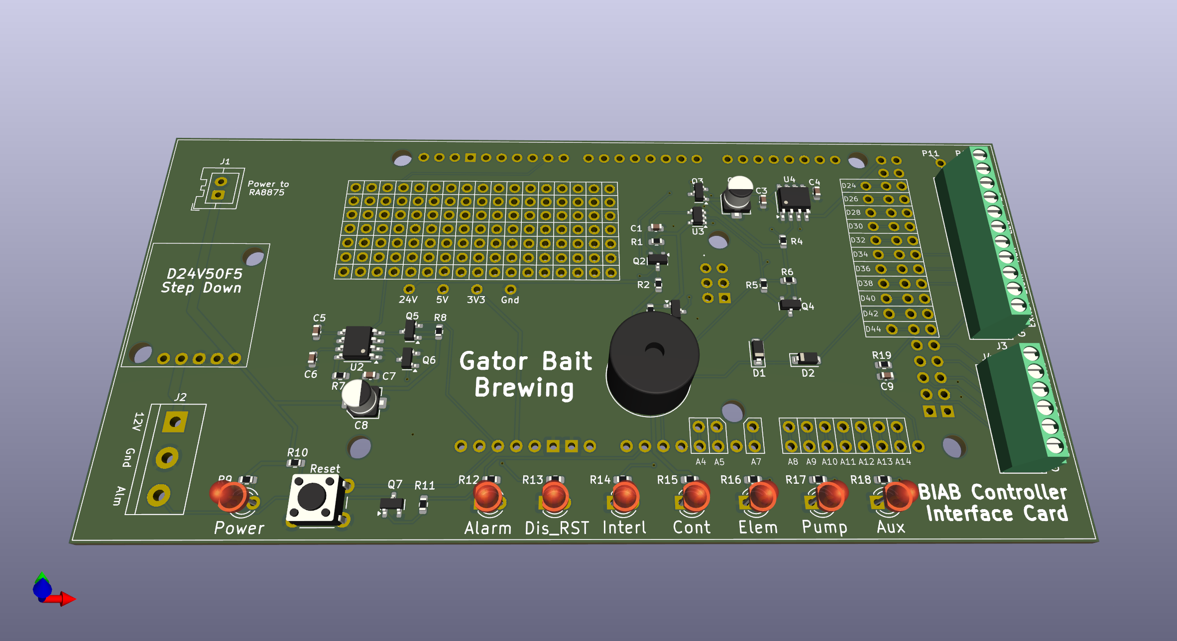
The circuit board layout is provided here for completeness. For additional information, place refer to the KiCad model.